Electronics & programming
Voltage (potential difference) is the electrical potential between 2 points, measured in Volts.
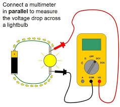
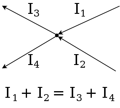
Current is the rate of flow of electrical charge at a point, measured in Ampere.
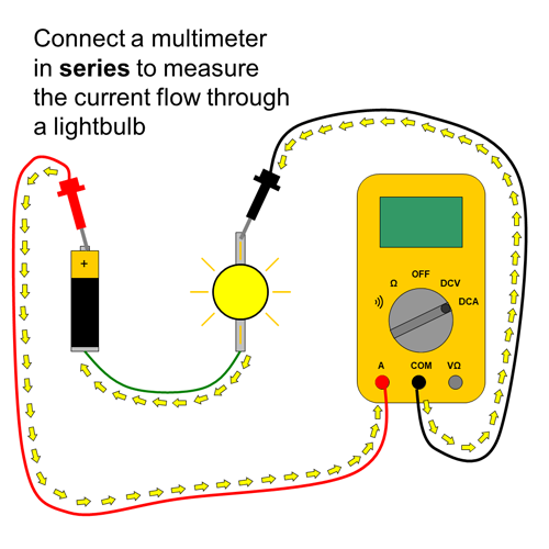
Resistance is the measure of the opposition to current flow in an electrical circuit, measured in Ohms.
Ohm's law.
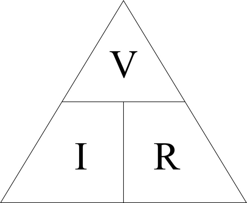
Voltage(V) = Current(I) * Resistance (R)
Ohm's law equation is useful in determining the appropriate resistor value to use to prevent damage to electrical components.
We made double ended alligator clip wires in order to provide a power source to our test board. It also serves as soldering practice.
We are provided with a meter of multicore 2 way cable. We split the ends and use a wire stripper to expose a bit of the wires.

Red wire stripped, black not stripped yet.
Next is wire tinning. This will hold the thin strands together and make it easier to connect the wire to other connectors. We prepare the wire for soldering by dipping it in flux, then using a soldering iron, melt a blob of solder onto the iron tip and spread it along the exposed wire.


First tinned the red wire, after which I cut a bit of the end off before repeating on the black wire.

Next is connecting the alligator clips. I first remove the rubber cover and slip it through the cable, making sure the colours match with the cables. I also sand the hole on the clip with sandpaper to prepare for soldering.

I then slip the bare wire into the hole of the alligator clip, and using pliers bend the back onto the cable to secure it to the clips. I then bend the cable flat and added some flux and solder the holes.
I also noticed the black clip is smaller than the red clip, So I double checked the rubber cover can fit the clip before soldering.

After this is just simply placing the cover over. I did this by using another clip to keep the mouth open so the cover can be slid in.

I then solder the other end with another pair of clips.

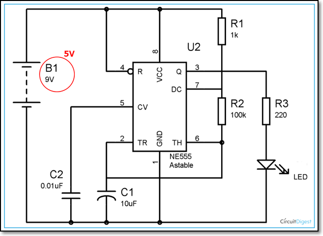
In this project we design a Astable 555 timer circuit, which will cause an LED to blink.
For this we will follow this circuit design.
We can design our circuit virtually with ThinkerCAD, to ensure everything works before creating it physically.
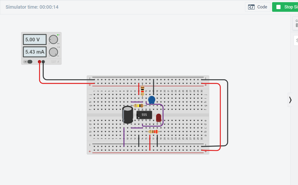
After designing on ThinkerCAD I redid the circuit, this time on a physical breadboard.
Once tested on the breadboard I can now transfer and solder the circuit to a stripboard.
Arduino is an open-source electronics platform based on easy-to-use hardware and software. Its affordability and easy to use system makes it ideal when implementing embedded systems into projects.
For the embedded programming assignments, we use an Arduino Uno to interface several I/O (Input and output) devices.
Input devices, also called sensors detect events or changes in its enviroment and sends information to other electronics. Most sensors give out analog signals (potentiometer, LDR, Water sensor, etc). Digital sensors transmits data in digital directly, like push buttons.
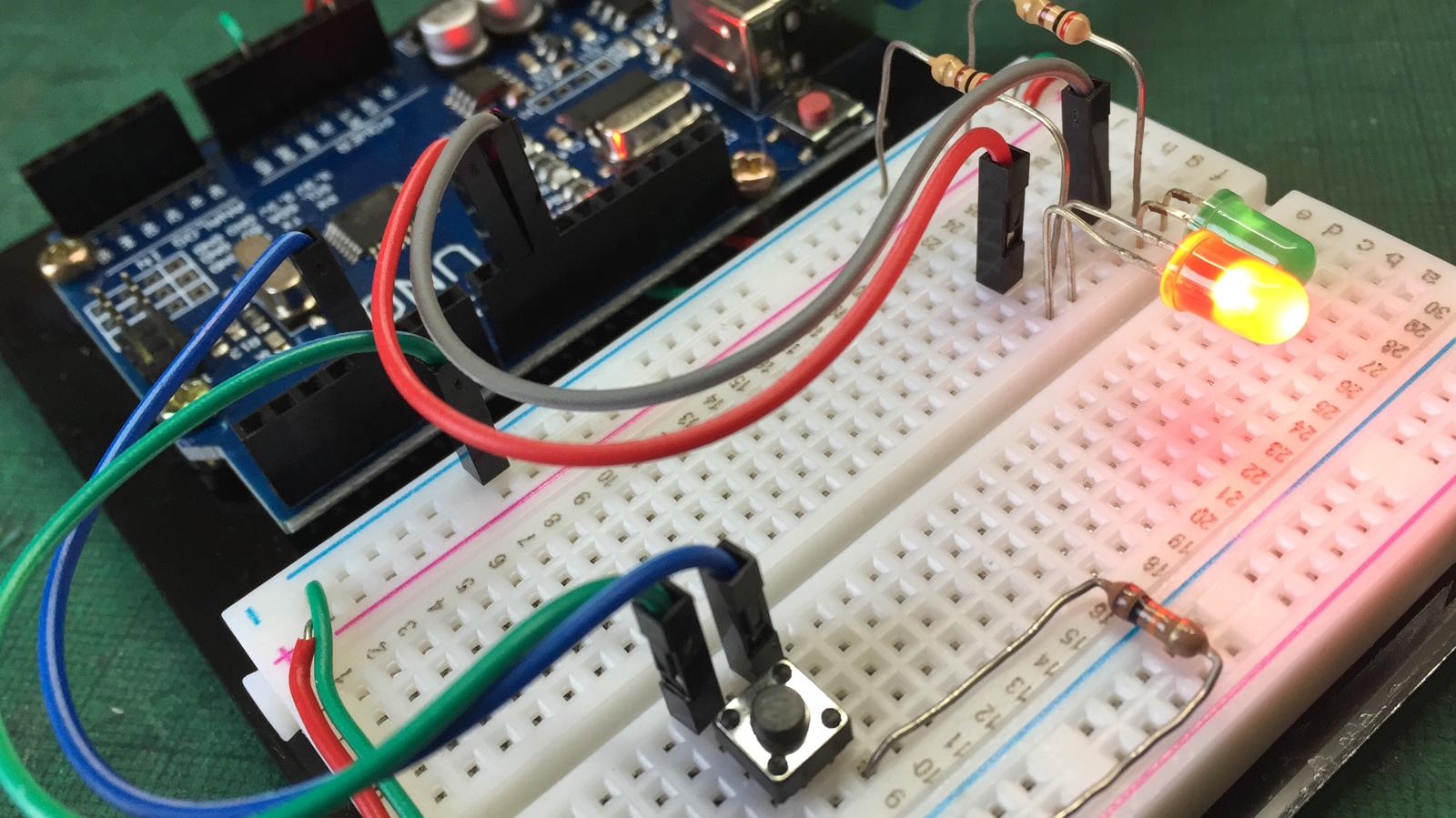
In this project, we are to control 2 LEDs with a push button using an Arduino UNO.
The LED's should turn on in this sequence:
First of all I design the circuit on ThinkerCAD:
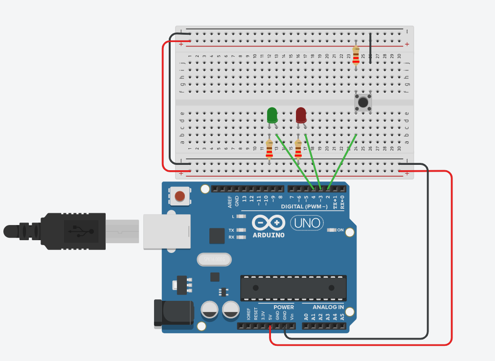
For the resistor values I used 200 ohm resistors connected to the LED and a 1k ohm resistor connected to the push button switch. The bush button is set up in active-high arrangement, meaning when the button is pressed a low signal (low voltage) will be sent to the pin input.
Another important thing to note is the pin output (positive) is connected to the LED anode. There are multiple methods of identifying the anode and cathode of an LED, such as the longer leg usually indicates the anode, or looking at the LED body, the leg closer to the flat edge indicates the cathode. Another easier way is running a small voltage through the LED, the anode must be connected the the positive and the negative connected to the cathode. Connecting it in reverse may damage it!
Then I write, test and troubleshoot the program on the website.
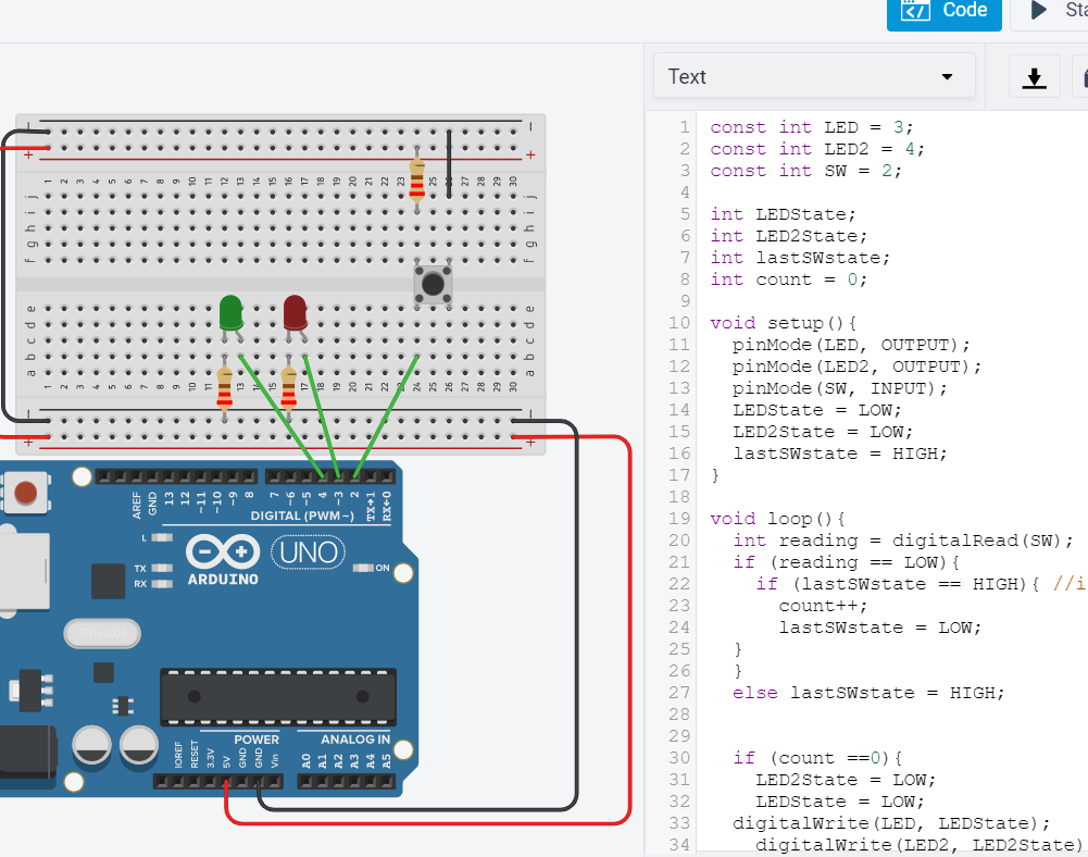
Here is the final program:
const int LED = 9;
  const int LED2 = 10;
  const int SW = 4;
  int lastSWstate;
  int count = 0;

  void setup(){
    pinMode(LED, OUTPUT);
    pinMode(LED2, OUTPUT);
    pinMode(SW, INPUT);
    lastSWstate = HIGH;
  }
  void loop(){
    int reading = digitalRead(SW);
    if (reading == LOW){
      if (lastSWstate == HIGH){ //if button press
        count++;
        lastSWstate = LOW;
    }
    }
    else lastSWstate = HIGH;

    if (count ==0){
    digitalWrite(LED, LOW);
      digitalWrite(LED2, LOW);
    }
    else if (count == 1){
      digitalWrite(LED, HIGH);
      digitalWrite(LED2, LOW);
    }
    else if (count == 2){
    digitalWrite(LED, LOW);
      digitalWrite(LED2, HIGH);
    }
     else if (count == 3){
    digitalWrite(LED, HIGH);
      digitalWrite(LED2, HIGH);
    }
    else{
      count = 0 ;
    }
  }
Note that I changed the pin numbers on the actual board compared to the ThinkerCAD simulator for a more neater circuit layout on the breadboard.
The program works by counting the number of times the button has been pressed, where for the number of times counted will toggle the state of the LEDs using if-else statements.
After testing on ThinkerCAD I recreate the circuit physically and upload the program on the arduino UNO.

While digital signals are discrete and changes in specific steps (High and Low), analog signals can vary continuously.
Arduino UNO has 6 analog pins A0-A5, which are used when interfacing analog input devices such as potentiometers, LDR (Light dependent resistors) and other sensors.
It uses an ADC (Analog to Digital Convertor) to convert an input voltage into a number, requiring a reference voltage and a n-bit ADC.
As Arduino does not have a built in DAC (Digital to Analog Convertor), we will use PWM (pulse width modulation) to vary the output voltage.
It works by modulating the width of the pulse of a square wave, changing its average voltage. A square wave thats high 50% of the time will have a 50% duty cycle PWM, while a continuous high output will be a 100% duty cycle.

The Arduino has 6 PWM ports, which has a "~" at the end of each number (3, 5, 6, 9, 10, 11)
Potentiometer and LED
The potentiometer controls the brightness of the LED.
I start by designing and programming the circuit on ThinkerCAD.

With the oscilloscope connected to the output you can view the PWM signal.
Code:
void setup()
{
  Serial.begin(9600);
  Serial.println("ready");
}

void loop()
{
  int reading = analogRead(A2);
  Serial.print("Reading = ");
  Serial.println(reading);
  delay(500);

  int digValue = map(reading, 0, 1023, 0, 255);
  analogWrite(9, digValue);
  Serial.print("\t");
  Serial.println(digValue);
  delay(500);

}
After which I implement on the physical breadboard.

You can see the change in output from the serial monitor:
The LDR resistance changes with the light intensity that falls on it. The program causes the RGB LED to change colour as light intensity detected by the LDR changes.

Using the same program, I swapped the LDR with a potentiometer, so you can control the colour of the LED by turning the knob.

Output devices, also known as actuators are components that move, control or display information. The behavior of output devices are determined by input devices.
Actuators can create movement with Stepper motors, servo motors and DC motors. Actuators that requires to display information can be LED displays, LCD displays and other light output devices. Actuators requiring control can be Relays and transistor drivers to drive high power circuits.
I interface a potentiometer to control the rotation of a positional servo motor.
The connection is simple: Potentiometer is connected to pin A0 and Servo motor connected to analog pin 9.
Program:
#include <Servo.h>

Servo servo1;

int potpin = 0;
int val;

void setup() {
  servo1.attach(9);
}

void loop() {
  val = analogRead(potpin);            // reads the value of the potentiometer (value between 0 and 1023)
  val = map(val, 0, 1023, 0, 180);     // scale it to use it with the servo (value between 0 and 180)
  servo1.write(val);                  // sets the servo position according to the scaled value
  delay(15);                           // waits for the servo to get there
}